
The 7 Most Common Sheet Metal Design Mistakes and How to Fix Them
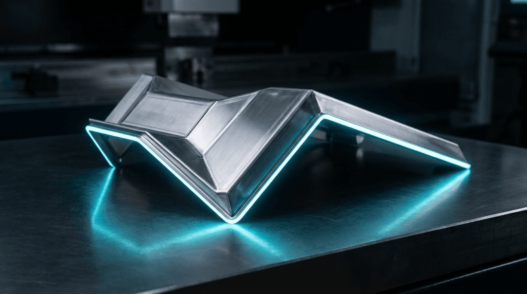
Sheet metal design mistakes lead to serious cost increases, lost time and quality problems in the production process. A small mistake made at the design stage can affect thousands of parts in series production. In our many years of sheet metal consultancy experience at Burak Engineering, we have observed engineers and designers falling into the same traps again and again.
In this guide, we take a detailed look at the 7 most frequently encountered critical problems among sheet metal design mistakes, together with practical solutions for each one.
1. Ignoring the Minimum Bend Radius: The Leading Sheet Metal Design Mistake
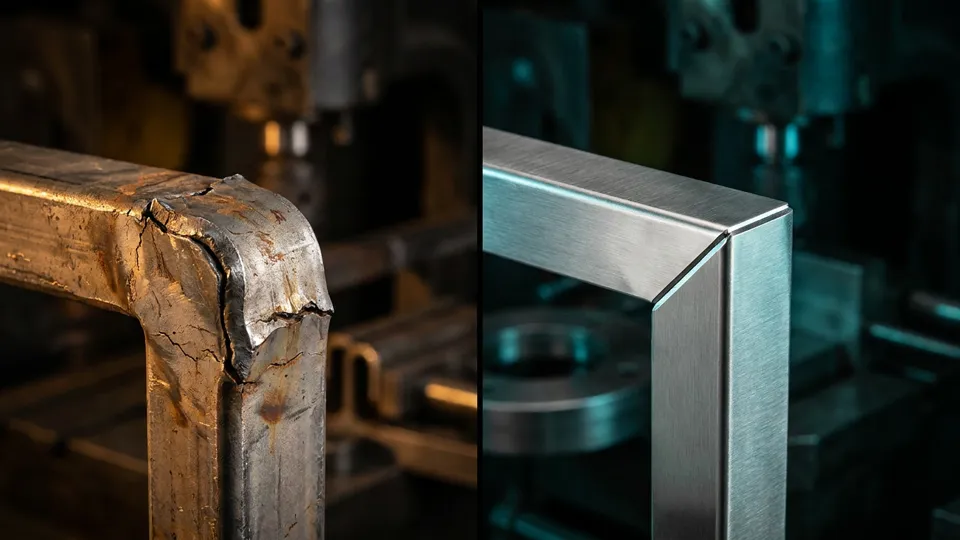
Every metal has a specific minimum bend radius, and going below this value causes cracks in the material. This is a critical issue particularly with stainless steel and high-strength alloys. As a general rule, the inside bend radius should be at least equal to the material thickness.
For high-strength steels this value can rise to 2-3 times the material thickness. In aluminium alloys, large differences can be seen depending on the temper condition. T6-temper aluminium requires a much larger bend radius than soft aluminium.
Solution: Request the technical data sheet (datasheet) from your material supplier. Run simulations in the SolidWorks Sheet Metal module with a correctly configured material library. Always perform a bend test at the prototype stage.
For detailed information, get in touch with us.
2. Setting the K-Factor Incorrectly
The K-factor is a critical parameter that defines the position of the neutral axis and directly affects the flat pattern dimensions. Using the wrong K-factor value causes dimensional deviations in production and results in parts that do not fit during assembly.
The K-factor varies with material type, thickness and bending method. For mild steel (DC01, DC04) a range of 0.40-0.45 is generally used. For stainless steel (AISI 304, 316) a range of 0.45-0.50 is recommended.
For aluminium, a range of 0.33-0.40 is appropriate.
Solution: Use the Gauge Table feature in SolidWorks to define the correct K-factor values for every material and thickness combination. Calibrate the K-factor by taking measurements on the first production batch. You can draw on the Engineering Toolbox as a reference source.
3. Failing to Plan the Bending Sequence
In complex sheet metal parts, the bending sequence is critically important. The wrong sequence can cause the part to collide with the tooling, make a bend impossible, or prevent the operator from positioning the part. Among sheet metal design mistakes, this is the problem that wastes the most time.
Especially with box-type parts, U-profiles and geometries containing multiple bends, production should never begin without sequence planning. After each bend, it must be checked whether the part’s new geometry is suitable for the next bend.
Solution: Simulate the bending sequence in SolidWorks. Run offline simulations in press brake software (Metalix cncKad, RADAN) to perform collision checks. As a general rule, work from the inside out and from small to large.
4. Tolerance Ambiguity and Sheet Metal Design Mistakes
Failing to specify tolerances on technical drawings creates confusion at the subcontractor and leads every manufacturer to apply its own standards. The result is inconsistency between parts and problems during assembly.
General tolerances on sheet metal parts should be defined according to the DIN 6935 or ISO 2768 standards. The bend angle tolerance is typically between ±0.5° and ±1°. The flat dimension tolerance varies between ±0.1 mm and ±0.5 mm.
Hole position tolerance can be achieved with ±0.05 mm precision.
Solution: Add a general tolerance table to every technical drawing. Specify special tolerances for critical dimensions. Eliminate ambiguity by using GD&T (Geometric Dimensioning and Tolerancing).
Discuss tolerance capabilities with your subcontractor in advance.
5. Not Accounting for Springback
Springback is the tendency of metal to partially return to its original form after the bending force is removed. Parts produced without accounting for this effect deviate from the intended angle. The springback effect is particularly pronounced in high-strength steels and stainless steels.
In 1 mm thick DC01 mild steel, springback is around 1-2°, while in AISI 304 stainless steel of the same thickness it can reach 3-5°. In high-strength steels (HSLA, DP) this value can climb to 5-8°.
Solution: Set up springback compensation on the press brake control units. Analyse post-bend springback with SolidWorks Simulation. Carry out a trial bend to measure the actual springback value and enter it into the CNC program.
6. Leaving Insufficient Hole-to-Bend Distance
Holes located too close to the bend line deform during bending and turn oval. This negatively affects the part’s functionality and blocks the passage of bolts or rivets during assembly. Among sheet metal design mistakes, this is the easiest one to prevent.
The minimum hole-to-bend distance is calculated with the following formula: minimum distance = 2 x material thickness + bend radius. For example, at 2 mm thickness with a 2 mm bend radius, the minimum distance should be 6 mm. If this distance cannot be achieved, a relief cut (slot) should be added along the bend line.
Solution: Check your design automatically using the SolidWorks DFMXpress tool. Prevent hole deformation by adding relief cuts. Create a design rules checklist and verify this distance on every new part.
7. Disregarding the Material Rolling Direction
The rolling direction of sheet metal directly affects its mechanical properties. Bends made parallel to the rolling direction increase the risk of cracking, because the material’s elongation capacity is lower in that direction. Bending perpendicular to the rolling direction should always be preferred.
The rolling-direction effect is very pronounced especially in thin sheets (0.5-1.0 mm) and high-strength materials. For parts requiring bends in two directions, placing the part at a 45° angle to the rolling direction can deliver acceptable results in both bend directions.
Solution: Ensure that parts are positioned according to the rolling direction in the nesting plan. Indicate the rolling direction with an arrow on the technical drawing. Request a rolling-direction certificate from your material supplier.
Conclusion: How to Prevent Sheet Metal Design Mistakes
These 7 sheet metal design mistakes can easily be prevented with the right knowledge and a systematic approach. The SolidWorks Sheet Metal module, the DFMXpress analysis tool and Metalix CAD/CAM software are your greatest allies in this process. At Burak Engineering, we provide sheet metal design consultancy, DFM analysis and production follow-up services.
Having a professional DFM check carried out before sending your designs to production delivers serious cost savings in the long run. Get in touch with Burak Engineering to receive a free preliminary assessment for your projects.

FAQ
Frequently Asked Questions
What is sheet metal design mistakes?
Sheet metal design mistakes: bend radius, relief cuts, hole distance, tolerances and flat pattern errors – the 7 most common and how to fix them.
1. Ignoring the Minimum Bend Radius: The Leading Sheet Metal Design Mistake: what should you know?
Every metal has a specific minimum bend radius, and going below this value causes cracks in the material. This is a critical issue particularly with stainless steel and high-strength alloys. As a general rule, the inside bend radius should be at least equal to the material thickness.
2. Setting the K-Factor Incorrectly: what should you know?
The K-factor is a critical parameter that defines the position of the neutral axis and directly affects the flat pattern dimensions. Using the wrong K-factor value causes dimensional deviations in production and results in parts that do not fit during assembly.
3. Failing to Plan the Bending Sequence: what should you know?
In complex sheet metal parts, the bending sequence is critically important. The wrong sequence can cause the part to collide with the tooling, make a bend impossible, or prevent the operator from positioning the part. Among sheet metal design mistakes, this is the problem that wastes the most time.
How can I work with Burak Engineering on sheet metal design mistakes?
Share your drawings and goals; we review your sheet metal design mistakes requirements and propose a suitable working model. Get in touch through the contact page.