SolidWorks Macro and Parametric Design Automation

SolidWorks Macro & Parametric Design Automation
SolidWorks Macro and Parametric Design Automation
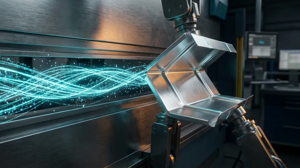
We turn repetitive CAD work in your engineering office into a controlled system. With SolidWorks macros, design tables and Excel-driven configurators, quotation models, flat patterns, drawings and BOM outputs are produced from a single source of truth instead of being rebuilt by hand for every order.
- VBA & SolidWorks API
- Design tables & configurations
- Excel product configurator
- Automatic DXF & flat pattern
- BOM and drawing automation
Definition
What are SolidWorks macros and parametric design?
A SolidWorks macro is a small program written in VBA or against the SolidWorks API that performs modelling, drawing and export steps automatically. Parametric design is the practice of building a model so that its geometry is driven by named dimensions, equations, design tables and configurations. Used together they let one master model produce an entire product family without redrawing anything.
In a manual workflow every new order starts from an empty part. Someone opens a similar file, saves it under a new name, edits the sketch, repairs the drawing views, exports the DXF and finally types the bill of materials into a spreadsheet. Each of those steps is a place where a wrong revision can slip into production.
In a parametric workflow the same product family lives in one controlled master model. Width, height, thickness, hole pattern and material are inputs. A macro reads those inputs, rebuilds the geometry, refreshes the drawing sheet, writes the title block, exports the flat pattern and generates the BOM in one run. The engineer reviews the result instead of producing it.
The official SolidWorks help documentation describes the API objects used for this work, and the VBA language reference covers the scripting side. Our job is to combine both into something your team can actually run every day.
The problem
Six bottlenecks that eat your engineering hours
Before we write a single line of code we measure where the time actually goes. In sheet metal fabrication and machine building the same six patterns come up again and again.
Modelling from scratch on every order
A similar product already exists, but nobody trusts it enough to reuse it. So a new file is built by hand and the family drifts further apart with every project.
Drawings that break when dimensions change
Views detach, dimensions dangle and section lines move. Repairing a drawing after a size change often takes longer than the modelling itself.
Manual DXF and flat pattern errors
Bend allowance, k-factor and grain direction are decided per file rather than per material. The laser receives geometry that does not match the press brake reality.
Bills of material that do not match
The BOM is typed into a spreadsheet, then edited again after a revision. Purchasing orders the wrong quantity and the assembly waits.
Quotation lead time is too long
A customer asks for a variant. Producing a credible price needs a model, a drawing and a nesting estimate, so the answer arrives days later.
Knowledge lives in one person
The rules that make the product manufacturable exist only in the head of a senior engineer. When that person is unavailable, the office slows down.
Scope
What SolidWorks macro and parametric design services cover
Every engagement is scoped to your product family and your existing files. These are the four blocks we deliver most often.
SolidWorks macro development (VBA & API)
- Batch export of DXF, DWG, STEP and PDF from assemblies
- Automatic drawing creation with your title block and standards
- Property and metadata writing for ERP and PDM integration
- Custom commands for repetitive modelling operations
- Error logging so a failed run tells you exactly what broke
Parametric models and template libraries
- Named dimensions, equations and global variables as the single source of truth
- Design tables and configurations for a full product family
- Sheet metal gauge tables tied to your real press brake tooling
- Reusable templates for parts, assemblies and drawings
- Naming and revision rules so files stay findable
Excel based product configurator
- Sales enters dimensions and options in a familiar spreadsheet
- The macro drives SolidWorks and returns model, drawing and DXF
- Rule checks stop impossible combinations before they reach the shop
- Instant weight, area and material consumption figures for pricing
- A quotation package produced in minutes instead of days
Automatic technical documents and BOM
- Bills of material generated directly from the assembly structure
- Balloon and exploded view documentation produced automatically
- Revision tables kept in sync with the model
- Export formats matched to your ERP import template
- One click regeneration after every design change
The process
Rollout in four steps
Automation fails when it is introduced as a big bang. We deliver it in short, measurable stages so the team keeps working while the system grows.
Analysis and measurement
We sit with your engineers, time the real workflow and pick the two or three tasks with the highest repetition. The output is a written scope with expected minutes saved per item.
Pilot implementation
One product family is converted into a parametric master model with its macro. You see real output on real orders before the wider rollout is approved.
Roll out and training
The remaining families are migrated, templates are standardised and your team is trained to run and adjust the system without external help.
Maintenance and improvement
SolidWorks versions change and so do your products. We keep the code compatible and extend it as new requirements appear.
The gain
Typical durations before and after automation
The figures below come from sheet metal and machine building projects with comparable part counts. Your own numbers are measured during the analysis stage.
| Task | Manual method | Macro / parametric |
|---|---|---|
| Exporting DXF files from a 20 part assembly | 80 – 100 minutes | 3 – 5 minutes |
| Modelling a new size variant for a quotation | 3 – 4 hours | 20 – 30 minutes |
| Filling drawing views and title block data | 30 – 45 minutes | 1 – 2 minutes |
| Preparing the bill of materials | 40 – 60 minutes | automatic |
| Regenerating all outputs after a revision | 1 – 2 hours | 5 – 10 minutes |
Audience
Who this service is for
Sheet metal manufacturers
Companies producing enclosures, panels, brackets and frames in many sizes, where the flat pattern and the press brake sequence must be right the first time.
Machine and control panel builders
Teams whose products share a structure but differ in dimensions and options, and whose quotation speed decides whether the order is won.
Engineering offices and project teams
Departments that deliver drawing packages to several customers and need consistent standards across every file they issue.
Engineering firms and subcontractors
Suppliers who must match a client specification exactly and prove traceability between model, drawing and delivered part.
If your engineering office repeats the same modelling and documentation work more than a few times a week, the investment usually pays for itself within the first quarter. If every project is genuinely one of a kind, we will tell you honestly that a template library is a better fit than a macro.
Checklist
Checklist before you start automating
Work through this list before any code is written. Most failed automation projects fail on the items below rather than on programming.
- Decide which product family is repeated most often and count how many variants it has.
- Agree the naming convention for parts, assemblies, drawings and exported files.
- Fix the gauge table and bend allowances against the tooling actually mounted on your press brake.
- Confirm the drawing template, title block fields and the standard your customers expect.
- Record who is allowed to change the master model and how a revision is approved.
- Check that the ERP or purchasing system can import the BOM format you plan to generate.
- Make sure every workstation runs the same SolidWorks version and service pack.
- Set a measurable target, for example cutting quotation preparation from four hours to thirty minutes.
The three mistakes we see most often
Automating a broken process
If the manual workflow is undocumented, the macro simply repeats the confusion faster. Clean the process first, then encode it.
Building a model nobody else can edit
Hundreds of unnamed dimensions and hidden relations create a file only its author can open safely. Naming and documentation are part of the deliverable.
Skipping the pilot
Converting forty families at once guarantees a rollback. One family, measured honestly, tells you whether the approach fits your office.
Core discipline
Design intent: why parametric work begins in the sketch
Whether a model will survive a dimension change is decided the minute the first sketch is drawn. Parametric modelling is not an add-on; it is a way of thinking that has to be set up from the start.
Design intent means deciding in advance how the model should behave when a given dimension changes. A model drawn without that decision falls apart at the first revision, with rebuild errors cascading down the tree.
Fully define the sketch
A single unconstrained line lets the geometry drift in an unpredictable direction as soon as a dimension changes. A fully defined sketch is the first condition of parametric work.
Relations before dimensions
Parallelism, concentricity and symmetry should be established before dimensions are added. Geometry held by relations is far more stable than geometry forced by numbers.
Keep references fixed
Sketches are tied to the origin and the default planes wherever possible. Sketches attached to neighbouring faces break when those faces move.
Keep the tree lean
A few meaningful features are more reliable than many small ones, and giving each feature a readable name shortens every future maintenance job.
These four habits prevent the majority of rebuild errors before they ever appear.
Decision table
Global variables, equations, design tables and configurations
Each parametric tool in SolidWorks solves a different problem, and a SolidWorks macro only multiplies whatever structure it finds. Choosing the wrong tool produces a model that works but cannot be maintained.
| Tool | Best suited to | Limitation |
|---|---|---|
| Global variable | Main dimensions repeated across several features | Does not express a rule on its own |
| Equation | Relationships between dimensions and manufacturing rules | Readability drops if overused |
| Design table | Many dimensional variants of the same product | Insufficient where topology changes |
| Configuration | Real variants created by suppressing features | Files grow heavy as the count rises |
| SolidWorks macro | Bulk generation of variants and outputs | Accelerates errors if the model has no rules |
The practical rule: use a design table when dimensions change, a configuration when features appear or disappear, an equation when a rule must be captured, and a SolidWorks macro when the output has to be produced repeatedly. Making that distinction early extends the useful life of the model considerably.
Questions
Frequently asked questions about SolidWorks macro and parametric design
How long does a macro project take?
A focused pilot on one product family usually runs three to six weeks from the first analysis meeting to a macro your team uses on live orders. A full department rollout across several families typically takes two to four months, delivered in stages so nothing stops while the work continues.
Do we need the Professional or Premium licence?
No. The SolidWorks API and VBA macro support are available in the Standard licence, which is enough for the great majority of automation work. Professional or Premium only becomes relevant if you also need the extra simulation, routing or PDM capabilities for other reasons.
What happens when we upgrade SolidWorks?
Well written macros survive version upgrades because they use documented API calls rather than screen coordinates. We test the code against your new version and adjust anything that a version change deprecated, which is part of the maintenance agreement.
Will the code belong to us?
Yes. The macro source, the parametric templates and the documentation are handed over to you at the end of the project. You are free to modify or extend them internally, and we provide the commented source rather than a locked binary.
Can it connect to our ERP system?
In most cases yes. The macro can write the bill of materials and part properties into the file format your ERP imports, or call an API if one is available. The integration depth is agreed during the analysis stage, because it depends on what your ERP exposes.
Keep reading
Related engineering guides
SolidWorks macro automation guide
How to record your first macro and turn it into a reusable tool.
SolidWorks sheet metal design
Flat patterns, bend allowance and manufacturable modelling rules.
Technical drawings, exploded views and BOM
Producing documentation the shop floor can actually work from.
Design for manufacturability (DFM)
Catching production problems while the design is still cheap to change.
Metalix cncKad and AutoNest
Turning approved geometry into efficient nesting and cutting programs.
Consultancy and system setup
Building the wider engineering system around your automated workflow.
Next step
Let us measure where your engineering hours are actually going
Send us one product family and the drawings you produce for it today. In a free thirty minute call we will tell you which parts of that workflow can be automated, roughly how much time it would save and what the first pilot would involve. If automation is not the right answer for your case, we will say so.
Solidworks macro: checklist
Use this checklist to review the solidworks macro steps covered on this page:
- What are SolidWorks macros and parametric design?
- Six bottlenecks that eat your engineering hours
- What SolidWorks macro and parametric design services cover
- Rollout in four steps
- Typical durations before and after automation
- Who this service is for
- Checklist before you start automating
- Frequently asked questions about SolidWorks macro and parametric design
If you want hands-on support with solidworks macro, get in touch.
FAQ
Frequently Asked Questions
What is solidworks macro?
SolidWorks macro development, parametric models and Excel configurators that automate DXF, drawing and BOM output. Engineering automation from Istanbul, Turkey.
What are SolidWorks macros and parametric design?
A SolidWorks macro is a small program written in VBA or against the SolidWorks API that performs modelling, drawing and export steps automatically. Parametric design is the practice of building a model so that its geometry is driven by named dimensions, equations, design tables and configurations.
Six bottlenecks that eat your engineering hours: what should you know?
Before we write a single line of code we measure where the time actually goes. In sheet metal fabrication and machine building the same six patterns come up again and again.
What SolidWorks macro and parametric design services cover: what should you know?
Every engagement is scoped to your product family and your existing files. These are the four blocks we deliver most often.
How can I work with Burak Engineering on solidworks macro?
Share your drawings and goals; we review your solidworks macro requirements and propose a suitable working model. Get in touch through the contact page.
Share your drawings and goals; we review your solidworks macro requirements and propose a suitable working model. Get in touch through the contact page.