Technical Drawing, Exploded View and BOM: The Complete Guide
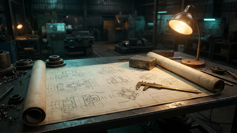
A technical drawing is the most critical document through which an engineering design is translated into the language of manufacturing. A correctly prepared technical drawing enables the subcontract manufacturer to produce the part without any ambiguity. In this guide we take a comprehensive look at drawing preparation, exploded view creation and bill of materials (BOM) management in the sheet metal field.
Technical Drawing Standards: ISO and DIN
International technical drawing standards ensure that drawings are understood universally. ISO 128 defines line types and thicknesses. The continuous thick line is used for visible edges, the thin dashed line for hidden edges and the chain (dash-dot) line for centre lines.
ISO 2768 is the general tolerances standard. It defines four tolerance classes: Fine (f), Medium (m), Coarse (c) and Very Coarse (v). For sheet metal parts the Medium class is usually applied. Specific tolerances must be stated for critical dimensions.
DIN 6935 defines special tolerances for bent sheet metal parts. Bend angle tolerance, linear dimension tolerance and bend line position tolerance are covered in detail in this standard. Agree in advance with your subcontract manufacturer on which standard will be used.
Creating Technical Drawings with SolidWorks Drawing
The SolidWorks Drawing module is the most efficient way to create a technical drawing automatically from the 3D model. Open a new drawing file via File > New > Drawing and select a template. A3 and A4 sheet sizes are the most commonly used formats for sheet metal parts.
To place views, you can drag and drop from the View Palette panel. The front view, side view, top view and isometric view are the basic views a standard drawing should contain. Sectioning with Section View and detail enlargement with Detail View are used frequently.
For sheet metal parts, adding a flat pattern view is very important. The Flat Pattern view makes it easier for the laser cutting operator to recognise the part. Bend lines and bend directions must be shown clearly in this view.
Dimensioning and Tolerance Indication
The basic rule of dimensioning is that each dimension is given only once and in the most suitable view. Define a reference plane or reference edge and prefer parallel dimensioning over chain dimensioning. Chain dimensioning causes tolerance stack-up.
For tolerance indication, using GD&T (Geometric Dimensioning and Tolerancing) to the ISO 1101 standard is the correct approach. Flatness, parallelism, perpendicularity and position tolerances are the geometric tolerances most frequently used on sheet metal parts.
Surface roughness symbols are indicated according to the ISO 1302 standard. On sheet metal parts the laser-cut surface typically has a roughness in the Ra 3.2-6.3 range, while the bent surface lies in the Ra 1.6-3.2 range. We covered the subject of tolerances in detail in our DFM analysis guide.
Complementing the Technical Drawing: Creating an Exploded View
An exploded view is a powerful documentation tool that visually communicates the assembly sequence and the relationships between parts. In the SolidWorks Assembly environment you can create an exploded view via Insert > Exploded View.
You can adjust the movement direction and distance of each part individually. To show the assembly sequence, explode the parts in logical groups. The part assembled first should be positioned innermost and the part assembled last outermost.
After creating the exploded view, insert it into the Drawing file and add balloon numbers and assembly sequence notes. The number in each balloon must match the item number in the BOM. This way the assembly technician can identify the parts easily.
Preparing the BOM (Bill of Materials)
The BOM is the table in which all the parts, materials and quantities that make up a product are listed. In SolidWorks Drawing you can create an automatic BOM via Insert > Tables > Bill of Materials. Part name, material, quantity and description information is pulled automatically from the Assembly file.
You can add or remove columns to customise the BOM. In sheet metal projects it is recommended to add thickness, surface finish, size and weight columns. Custom information defined via Custom Properties is reflected in the BOM automatically.
Two types are available: the Indented BOM and the Flat BOM. The Indented BOM shows sub-assemblies hierarchically. The Flat BOM presents all parts as a flat list. It is usually the Flat BOM that is sent to the subcontract manufacturer.
Technical Drawing and File Package: Sending to the Subcontract Manufacturer
A complete file package should contain the following documents. Drawings are sent in PDF format with all views, dimensions and tolerances. DXF files contain the flat pattern geometry for laser cutting. STEP or Parasolid files are included as the 3D model reference.
The BOM is sent in Excel format together with material, quantity and special notes. The assembly instruction contains the exploded view and the assembly sequence explanations. The quality control plan defines the critical dimensions and acceptance criteria.
In our SolidWorks sheet metal design guide we explained the DXF export process in detail. A complete file package greatly reduces manufacturing errors and delays.
Conclusion: Burak Engineering Technical Drawing Services
Professional technical drawing preparation is a critical process that directly affects the success of sheet metal production. Dimensioning to ISO standards, correct tolerance indication, an exploded view and a complete BOM strengthen communication with the subcontract manufacturer and prevent errors.
At Burak Engineering we provide engineering drawing with SolidWorks and AutoCAD, exploded view creation, BOM preparation and file package preparation services.
You can reach us via our contact page to receive a free preliminary assessment for drawing and documentation services.

FAQ
Frequently Asked Questions
What is exploded view and bom?
Exploded view and BOM in technical drawings with SolidWorks: views, dimensions, balloons, item numbers and clear assembly documentation.
Technical Drawing Standards: ISO and DIN: what should you know?
International technical drawing standards ensure that drawings are understood universally. ISO 128 defines line types and thicknesses. The continuous thick line is used for visible edges, the thin dashed line for hidden edges and the chain (dash-dot) line for centre lines.
Creating Technical Drawings with SolidWorks Drawing: what should you know?
The SolidWorks Drawing module is the most efficient way to create a technical drawing automatically from the 3D model. Open a new drawing file via File > New > Drawing and select a template. A3 and A4 sheet sizes are the most commonly used formats for sheet metal parts.
Dimensioning and Tolerance Indication: what should you know?
The basic rule of dimensioning is that each dimension is given only once and in the most suitable view. Define a reference plane or reference edge and prefer parallel dimensioning over chain dimensioning. Chain dimensioning causes tolerance stack-up.
How can I work with Burak Engineering on exploded view and bom?
Share your drawings and goals; we review your exploded view and bom requirements and propose a suitable working model. Get in touch through the contact page.