What Is Design for Manufacturability (DFM) Analysis? Why Is It Critical in Sheet Metal?

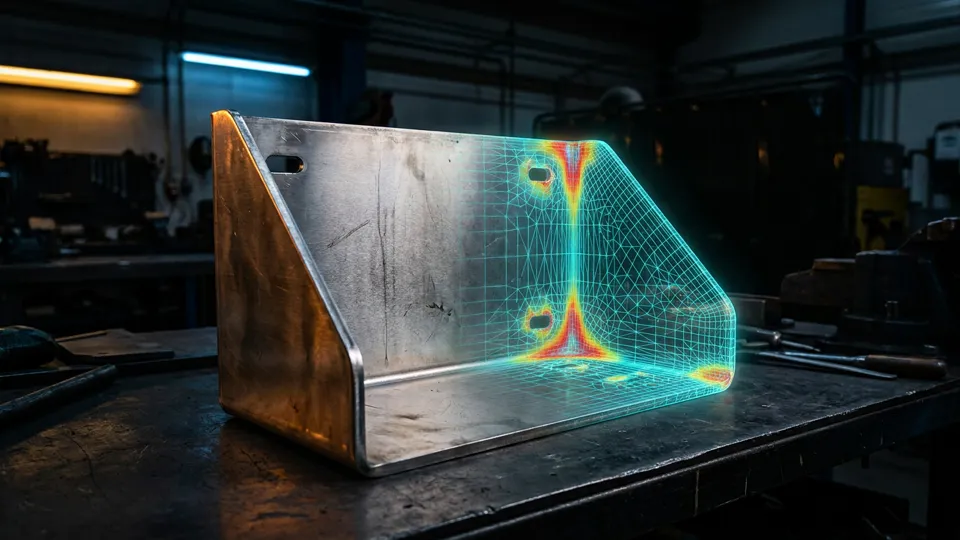
Design for manufacturability (DFM) analysis is a systematic engineering approach that takes the requirements and constraints of the manufacturing process into account at the design stage. In sheet metal production, design mistakes become expensive once manufacturing starts. By applying design for manufacturability (DFM) analysis, you catch these mistakes at the design stage and reduce cost.
What is DFM?
DFM (Design for Manufacturability) is the practice of optimising geometry, tolerances and material choices at the design stage to cut production cost and defect risk. In sheet metal, DFM covers bend radii, hole-to-edge distances, scrap rate and weld access.
What Is Design for Manufacturability (DFM) and Why Is It Necessary?
DFM is an engineering discipline that evaluates the manufacturability of a design and provides improvement recommendations. The goal is to design products that are easy to manufacture, low in cost and high in quality. When production starts without a DFM analysis, tooling changes, extra labour, increased scrap and delivery delays become inevitable.
According to research, 70-80% of a product’s cost is determined at the design stage. Changes made after the design is complete cost 10-100 times more than changes made during the design stage. This is why applying DFM early is critically important.
In the sheet metal industry, design for manufacturability (DFM) analysis covers the entire range of laser cutting, CNC punching, press brake bending, welding and assembly processes. Each manufacturing method has its own specific rules and constraints.
Sheet Metal DFM Checklist: Cutting Rules
The basic DFM rules for laser cutting and CNC punching operations are as follows. The minimum hole diameter must be equal to or greater than the material thickness. For example, for a 1.5 mm thick sheet, the minimum hole diameter is 1.5 mm.
Smaller holes can be produced with special tooling or by laser, but the cost increases.
The minimum distance between edges must be 2 times the material thickness. The minimum distance from a hole edge to the part edge is 1 times the material thickness. If these distances are not maintained, deformation occurs during cutting.
For narrow slots, the minimum width must be equal to the material thickness. Slots that are too narrow degrade laser cutting quality and make part cleaning more difficult. Sharp internal corners should be avoided in the outer contour geometry, and a minimum radius of R0.5 mm should be applied.
Sheet Metal DFM: Bending Rules and Design for Manufacturability Analysis
The DFM rules for bending operations are the most comprehensive part of the design for manufacturability (DFM) process. The minimum bend radius must be equal to the material thickness. The minimum distance from the bend edge to a hole centre is calculated with the formula 2 x thickness + bend radius.
The minimum flange height must be greater than half of the V-die opening. For example, if a 16 mm V-die is used, the minimum flange height must be above 8 mm. Shorter flanges carry a risk of slipping during bending.
For opposing bends, the minimum flat distance (web) must be at least 2 x V-die opening + material thickness. This rule is frequently violated in Z-profile and U-profile designs and causes problems in production. The throat depth of the press brake must also be taken into account.
Joining and Assembly DFM Rules
In welded joints, accessibility is the most important DFM criterion. Sufficient clearance must be left so that the welding gun can reach the joint. For spot welding, a minimum flange width of 12 mm is recommended.
In riveted and bolted joints, hole tolerances determine ease of assembly. For an M6 bolt the hole diameter is 6.5 mm, and for M8 it is 8.5 mm — the standard clearance hole sizes. For locating holes, on the other hand, the exact nominal diameter is used and the hole tolerance must be H7.
In press-fit nut and rivet nut applications, the material thickness must meet the minimum requirements. The minimum thickness values in the PEM nut manufacturer’s catalogue must be observed. You can access this data on the official PEM website.
Automatic Design for Manufacturability (DFM) Analysis with SolidWorks DFMXpress
SolidWorks DFMXpress is a built-in tool that automatically checks your design against DFM rules. It includes ready-made rule sets for milling, turning, sheet metal and injection mould designs. Issues found in the analysis are marked visually on the model.
In sheet metal mode, DFMXpress performs the following checks: minimum bend radius, hole-to-bend distance, minimum flange height, narrow slot width and sharp corner check. For every issue found, an explanation and a recommended value are provided.
You can export the DFMXpress results as a PDF report and share it with your subcontract manufacturer. This report strengthens the communication between designer and manufacturer and prevents misunderstandings.
How Does the DFM Process Work?
A systematic DFM process consists of five steps. In the first step, the designer completes the 3D model and the technical drawings. In the second step, the DFM specialist reviews the model against the manufacturing constraints.
In the third step, the problem areas are reported in detail.
In the fourth step, the designer makes the necessary revisions, and in the fifth step the revised design is checked again. This cycle continues until production approval. At Burak Engineering, we provide professional support at every stage of this process.
In the DFM report, a priority level (critical, high, medium, low) is assigned to every issue. Critical issues are errors that prevent manufacturing, high-priority issues are errors that increase cost, and medium-priority issues are conditions that affect quality.
Conclusion: Reduce Cost and Increase Quality with DFM
Design for manufacturability (DFM) analysis must be an integral part of the sheet metal design process. Applied at an early stage, DFM can reduce manufacturing cost by 20-50%, shorten delivery time and improve part quality. The SolidWorks DFMXpress tool and professional DFM consultancy are your greatest allies in this process.
At Burak Engineering, we provide detailed DFM analysis, design revision and production follow-up services in SolidWorks and AutoCAD. For your projects, reach us via our contact page.

FAQ
Frequently Asked Questions
What is dfm analysis?
DFM analysis explained for sheet metal: bend limits, tooling access, tolerance stack-up and cost drivers checked before production starts.
What Is Design for Manufacturability (DFM) and Why Is It Necessary?
DFM is an engineering discipline that evaluates the manufacturability of a design and provides improvement recommendations. The goal is to design products that are easy to manufacture, low in cost and high in quality.
Sheet Metal DFM Checklist: Cutting Rules: what should you know?
The basic DFM rules for laser cutting and CNC punching operations are as follows. The minimum hole diameter must be equal to or greater than the material thickness. For example, for a 1.5 mm thick sheet, the minimum hole diameter is 1.5 mm.
Sheet Metal DFM: Bending Rules and Design for Manufacturability Analysis: what should you know?
The DFM rules for bending operations are the most comprehensive part of the design for manufacturability (DFM) process. The minimum bend radius must be equal to the material thickness.
How can I work with Burak Engineering on dfm analysis?
Share your drawings and goals; we review your dfm analysis requirements and propose a suitable working model. Get in touch through the contact page.